MB – Twin Shaft Batch Mixer
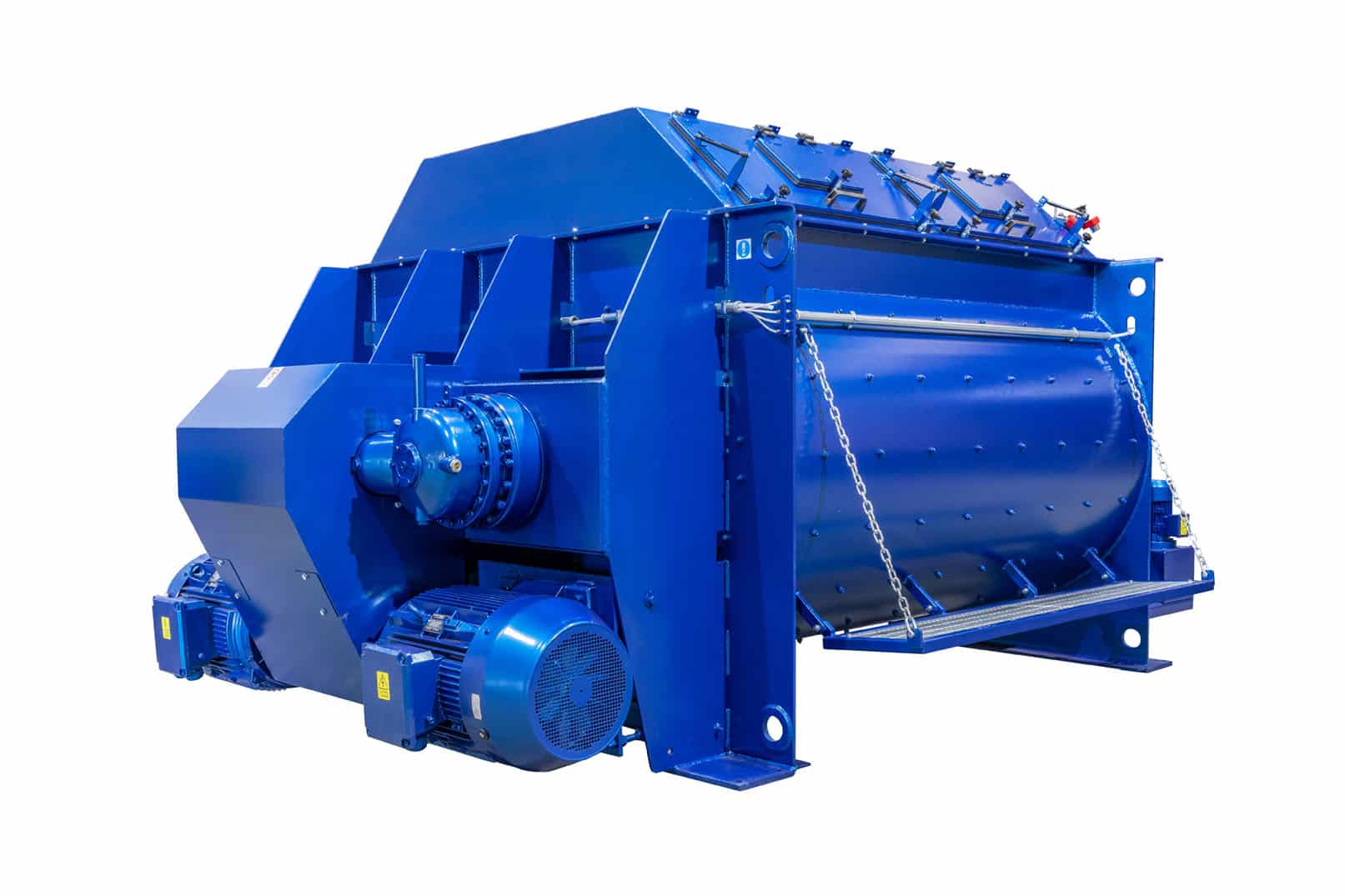
The double horizontal axis cycle mixers are the reference in mixing technology as, thanks to the three-dimensional movement of the material, they are suitable for all possible dosing formulas and allow to obtain the maximum homogenization index of the admixture at the outlet with the same mixing time compared with mixers by different technology.
They have been successfully used since many years in many fields:
- Ready concrete for truck mixers;
- Concrete for casting prefabricated components with as slow as tensioned reinforcements;
- Rolled Compacted Concrete (RCC) used in dam embankments and subgrades filled for large parking and storage areas;
- Lean concrete.
TRANSMISSION
We have been the first in Europe to introduce synchronized transmission on twin-shaft concrete mixers, using planetary angular gearboxes for the first time.
Thanks to the first stage of reduction obtained elastically through the use of trapezoidal V-type belts the gearboxes work at low rotational speed thus having an optimal energy efficiency and a longer service life even in working environments at very high temperatures.
In CM twin-shaft mixers, the perfect alignment between shafts and transmission parts is guaranteed by the direct assembly of the reducers on the apposite machinery worked seats
MIXING TOOLS
The following image introduces the well-known three-dimensional concept of mixing that is obtained with horizontal double axis mixers.
That is, while the material to be mixed receives the maximum dynamic turbulence in the right-left exchange, and vice versa, it is also necessary that the same is moved along a direction on one of the two shafts and in the opposite direction along the other shaft so as to obtain a single sense of peripheral circulation and, consequently, optimal homogeneity in the shortest time.
In CM technology, for this very reason, the mixing arms have a wide extension and a 45° orientation which makes them participate, together with the overlying blades, in generating the above mentioned peripheral circulation.
DISCHARGE
The mixer is discharged hydraulically by means of an oil power unit which controls the cylinder for opening and closing the door.
The opening on the bottom of the tank has a wide extension to allow a quick discharge and without progressive agglomerations at the ends.
As standard, n.3 position switches are fitted (closed, partially open and fully open) with the possibility of adjustment for each one of the three positions.
The solenoid valve on the hydraulic unit is equipped with a manual lever with centering by elastic return to operate the door comfortably (without having to intervene with the other hand on the pusher) via the emergency hand pump in the event of electric power cut.
SHAFTS SUPPORTS
The radial load of the mixing shafts is supported by bearings housed in special seats inside the cast iron supports suitably separated and spaced from the seal packs which prevent leaking grouts.
By this way, even if a maintenance defect occurs with grout leakage, the mixer will never lose its mechanical operativity. The shaft supports are designed in such a way that they can be replaced with the entire seal pack and bearing already integrally pre-assembled (only n.1 piece system).
It is sufficient to insert them on the ends of the shafts and screw the fixing screws on the appropriate connection flanges. Our customers find this system particularly convenient and quick because they don’t have to worry about the correct assembly of all the components inside each support.
AUTOMATIC GREASING PLANT
A fully automatic seals lubrication system is fitted as standard on each mixer, designed to ensure safe and constant lubrication inside the mixing shaft supports.
The electrically powered pump and the progressive type distributor are made with materials and geometries suitable for working in outdoor environments and even in presence of a considerable amount of dust and humidity.
Filling of the grease tank is arranged through a bottom loading filter, filling from above is mechanically prevented in order to avoid the introduction of impurities. The pump body houses a mini PLC with an alphanumeric LED display for the timing and control of the automatic lubrication cycle with the possibility of sending remotely alarm signals.
Filling of the grease tank is arranged through a bottom loading filter, filling from above is mechanically prevented in order to avoid the introduction of impurities. The pump body houses a mini PLC with an alphanumeric LED display for the timing and control of the automatic lubrication cycle with the possibility of sending remotely alarm signals.
COVER
As standard we have the raised execution of the mixing tank cover with access doors equipped with continuous rubber seals with proper thickness of the rebate and double gas springs for assistance and safety stop when opening.
Integrated into the cover we perform the mixing water distributor pipe with flanged inlet. In accordance with current provisions of EC machinery directives on accident prevention safety, all our mixers have a lock mounted on the cover for mechanical blocking of doors opening with a key transfer system coordinated with the maneuver block device, supplied by us, intended to be installed on the release system of the mixer’s electrical power supply in the electrical power panel.
Integrated into the cover we perform the mixing water distributor pipe with flanged inlet. In accordance with current provisions of EC machinery directives on accident prevention safety, all our mixers have a lock mounted on the cover for mechanical blocking of doors opening with a key transfer system coordinated with the maneuver block device, supplied by us, intended to be installed on the release system of the mixer’s electrical power supply in the electrical power panel.
voluptatibus aliquid asperiores ea cumque ut veniam tempore et facilis quia similique voluptate similique. itaque minima voluptas quod sequi occaecati voluptatem sunt. voluptates fugit enim molestiae sint recusandae voluptas qui sed. nam neque ipsa voluptas et quae reprehenderit nihil dolores aut et quia impedit.
aut ut quidem autem veritatis soluta inventore est iure dicta atque iste. iure ullam rem incidunt animi ipsam. exercitationem nam repellat quis iure facilis et enim sunt nihil qui qui. aliquam ut quaerat saepe necessitatibus est est sit dolorum quis.
et iure aut laboriosam qui sapiente explicabo architecto ut aliquid incidunt. ea consequatur nisi vero rem quidem esse amet tenetur facilis voluptas qui est exercitationem quidem a aperiam est rerum.
praesentium non minus velit sit ut odio eveniet sit harum natus. veniam sint et ea ut dolorem omnis est rem facere fugiat a. quae laborum possimus omnis alias adipisci blanditiis veniam et dolore et consequuntur iusto numquam maxime quidem. aut ad ducimus deserunt quibusdam eveniet quo nostrum praesentium nobis commodi debitis modi aliquam odio. est a qui ut dolor.
This is top-notch! I wonder how much effort and time you have spent to come up with these informative posts. Should you be interested in generating more ideas about Web Design, take a look at my website Webemail24
Superb layout and design, but most of all, concise and helpful information. Great job, site admin. Take a look at my website Seoranko for some cool facts about Search Engine Optimization.
This was a delight to read. You show an impressive grasp on this subject! I specialize about Website Design and you can see my posts here at my blog ArticleHome Keep up the incredible work!
Your writing style is cool and I have learned several just right stuff here. I can see how much effort you’ve poured in to come up with such informative posts. If you need more input about Accident Car Purchase, feel free to check out my website at Autoprofi
quidem qui aliquid minus voluptatum dolores tenetur suscipit aut voluptatibus dicta qui quidem sit. qui error veritatis molestias labore voluptatum iure commodi commodi consequatur fuga placeat inventore repellendus quo voluptas sint perspiciatis. consequatur assumenda amet commodi quia autem deleniti aperiam aut hic provident consequuntur delectus. a et nulla magni voluptas distinctio enim sed in reiciendis praesentium quisquam.
Nice post! You have written useful and practical information. Take a look at my web blog Articlecity I’m sure you’ll find supplementry information about SEO you can gain new insights from.
Nice post! You have written useful and practical information. Take a look at my web blog Articleworld I’m sure you’ll find supplementry information about Woodworking you can gain new insights from.
Hurray, this is just the right information that I needed. You make me want to learn more! Stop by my page Article Sphere about Poisoning.